Bearings vs. Lubricants_ Regreasing
Commenting to Ana Maria Delgado CRL with LUDECA, about the bearings and the lubricants that keep them operating, it occurs to me to write about a point of view that few people observe.
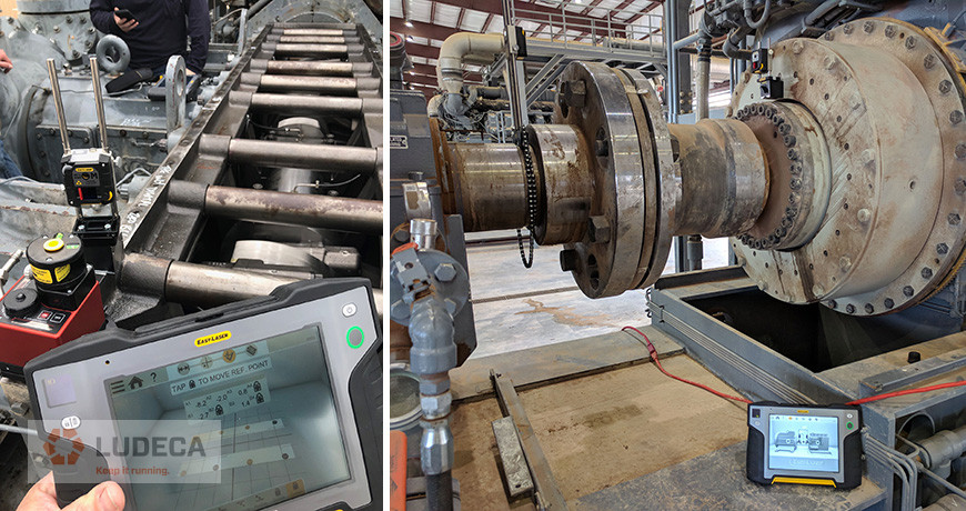
Two new hires called into our office for help with an alignment they were doing with a newly bought Easy-Laser XT laser shaft alignment system. Fortunately, our chief engineer was able to remotely guide them through two successful gearbox-motor alignments. There was still an issue: these gentlemen were inexperienced and being tasked with aligning 20 additional similar setups for cooling towers, in peak Texas heat. The first alignment revealed that our motor, Machine To Be Moved (MTBM) was both base- and bolt-bound. The second alignment also found the motor to be both base- and bolt-bound. Every single cooling tower had identical gearboxes and identical motors that sat on identical “frames”. By the third alignment, a clear pattern formed. This was no coincidence, the jackshafts were 110 inches long, with machines that weren’t centered prior to installation. Small amounts of angular misalignment at the gearbox are enough to cause a bolt- and base-bound condition as the offset produced by the angularity is magnified across the long distance of the jackshaft’s length, making the resulting correction to be performed too large at the motor. An angularity of 0.5 mils/inch is enough to cause a 55-mil offset between the machine shafts at a 110″ separation. It is apparent that it doesn’t take much angle to run out of space in the anchor bolt holes at the motor. The motor sat higher than the gearbox while both machines sat angled slightly downwards, looking towards the center between them.
After realizing they were bolt-bound many experienced alignment technicians would elect to use “Chicago” bolts or undercut bolts, which are designed to allow for a little additional freedom of horizontal movement of the machine. Obtaining them likely would waste several hours, even with a machine shop on site. Another approach is to drill bigger holes in the feet. However, our two junior aligners saved on what could have amounted to several days over the course of all 20 alignments by instead performing optimal moves. An “optimal” move is a small adjustment made to the Stationary Machine (the gearbox in this case) that eliminates the need for the large projected corrections at the Motor. It is the smallest feasible move that will accomplish this objective. In these cases, both front feet were brought up, which is easy to do, since adding shims is always easier than removing them if they aren’t there to start with! This saves time and is generally the most efficient approach to the base-bound situation. In this case, the gearbox was free to move, no piping or another machine coupled to it, so it was a no-brainer. Undercutting bolts is popular because piping and electrical conduit along with other factors make it difficult and, in some cases, impossible to move one of the machines. In any case, an optimal move is worth considering at the very least. As long as your stationary machine is able to make the SMALL move necessary you will save yourself time. Very little risk considering it, bountiful rewards if it makes sense. It is up to the technician to use their judgement and experience to determine if this is possible and worth the effort.
The third alignment needed two vertical moves to get it within Precision (ANSI/ASA S2.75-2017) Tolerance. The first correction was to shim both gearbox and motor front feet up, this got rid of the base-bound condition at the motor. The second move was to shim all four motor feet up. One horizontal move was necessary via gearbox to get out of bolt-bound condition, no jackbolts on the machine so a hammer was used. Every setup was the same, allowing our junior aligners to employ the template feature of their XT laser system and save more time there as well.
by Ana Maria Delgado, CRL
John Garrison is a SDT Level One Trained Ultrasound Inspector working as a Melt Shop Mechanical Technician in Alabama. This is part of his reliability journey as told by him.
As a mechanic in charge of a portion of the mill, safety and reliability are a must for myself, my company, and our customers. Giving our Operations group the best equipment and training possible are key to our success. For years we have outsourced the vibration, oil, and thermal analysis of our predictive maintenance program, and for years we have thought it was acceptable. But I can recall many occasions when components said to be good, turned out to be bad, or components said to be bad, turned out good. It was clear that our reliability program needed more.
I was approached by management and asked to lead an ultrasound campaign to improve our reliability program. The first thing we did was buy an SDT270 unit. When it arrived, I found myself staring at an expensive, little blue box which I had no clue what to do with. Shortly after I discovered SDT had a Live Online Level 1 Class starting soon, so I registered. I was pleased with all the additional on-demand webinars, lessons, and hours of learning from experienced reliability professionals that also came with the course.
I would recommend this course to anyone interested in becoming more familiar with ultrasound regardless of current skill set. There is something to be learned for all levels of ultrasound inspectors. While some classes make you feel like a prisoner voluntold to be there, not here. It is fun, engaging, and flourished with a plethora of useful knowledge and information. In the short 8 weeks of this class, I have found several failing components in our mill. I’ve been able to prevent unplanned downtime multiple times by planning to change the components on our time rather than running them to failure.
Click here to continue reading the entire article, “Stories From the Melt Shop” to learn about John Garrison’s reliability journey and how ultrasound can help!
Thank you SDT Ultrasound Solutions for sharing this testimonial and case study with us!
by Diana Pereda
Having taken an inventory of the assets in your plant, you have identified the right tools and training that are needed to minimize unplanned work and avoid creating new defects. Even better, you’ve done some economic analysis, using conservative values, which showed less than a one-year payback and projected substantial recurring annual savings through condition monitoring (CdM) and precision maintenance (PcM).
With the strategy and economic analysis in hand, you’ve convinced your plant manager that CdM and PcM are the keys to driving reliability and profitability. The plant manager funds your equipment and training request. Over the next several months you optimize your interval-based and condition monitoring tasks, train your team members and create CdM routes and train your team on precision maintenance practices.
The CdM and PcM programs start out great. Your team identifies and resolves defects that might have gone unnoticed and perhaps catastrophically failed. The plant manager is happy, your team feels like they’re doing good work. Things are great.
Unfortunately, there is a property of all systems in nature. Systems tend to move from high states of energy to lower states of energy over time. Your CdM and PcM ‘systems’ are no different. As the energy dissipates, the only way to restore the system is to put energy into it.
Leaders have a central role in adding energy to keep systems functioning at a high level. There are three things leaders must do:
Culture is what most people do most of the time. What people do are behaviors. Behaviors are based on long-term memories. Long-term memories are formed as short-term learning is consolidated through repetition. Training loads information into short-term memory. Practice converts short-term to long-term memories. Additional practice generates habits. When enough people have the same habits, those habits become the culture.
Leaders play a role in developing a culture in two ways. First, by providing direction, guidance, and resources. Direction includes mission, vision, values, and objectives. The guidance includes policies, plans, processes, procedures, and measures. Resources include funding, training, equipment purchases/replacements, and time for people to achieve and maintain habits.
Second, leaders develop and reinforce culture by applying productive leadership. Leaders should want to be leaders and want to be accountable. They need to learn and apply leadership roles, leadership attributes, and leadership skills. They should understand and properly apply sources of position and personal power. Leaders must also understand how to influence others based on needs and motivations. And leaders should set motivating goals. More information on these leadership elements can be found in my book, The Productive Leadership System.

Providing what’s needed for the team to perform means making sure your team has what they need to continue carrying out your direction and guidance. Turnover happens. People retire, get promoted, move to other positions, etc. Make sure there is good support in place to train new people and upgrade the skills of current technicians. Leaders have a role in this by planning, budgeting, and defending expenditures for training, replacing/upgrading tools, calibrating sensors, and upgrading software and firmware.
Leaders have a role in keeping the focus on the big picture by identifying and communicating matters related to the CdM and PcM programs. There can be counter-productive matters like operations not allowing time for rotating equipment to be precision aligned or balanced, or not heeding a warning that a bearing is about to fail. Communicate when positive things have occurred; a 50% increase in critical motor mean time between failure, 15% reduction in unplanned work orders, and 5% reduced maintenance costs as a percentage of the total cost.
Thank you Tom Moriarty with Alidade MER, Inc. for sharing this excellent and informative piece with us!
by Diana Pereda
In recent years, “Defect Elimination” has become a hot topic in the reliability world. But what exactly does defect elimination mean? How does it differ from other maintenance practices? Is it more than just a new way to describe planned and predictive maintenance?

Let me start by answering a more basic question. What is a defect? According to Merriam Webster’s online dictionary, a defect is defined as “an imperfection that impairs worth or utility”. The simple definition of a defect that we have used for the past 25 years in The Manufacturing Game® workshops is “Anything that erodes value, reduces production, compromises health, safety or environmental performance or creates waste”. Or in the words of the fictional Chance Brooks, plant manager turned corporate manager in the book Don’t Just Fix It, Improve It “…I came to regard defects as my real enemy. I always thought of them as the little imperfections that caused all of our problems and upsets. Some were big and some small, but when they lined up in just the right way… kaboom!!! A catastrophe would hit.”
A lot of time and attention has been paid to breaking the reactive maintenance cycle – equipment fails, operations call maintenance, maintenance repairs the equipment and turns it back over to operations – rinse and repeat.
Many organizations now perform time-based preventive maintenance, use predictive technologies, and perform operator rounds, all to find defects when they are. Then effective planning (the what, why, and how of the job) and scheduling (the when and by whom of the job) are employed to remove those defects prior to the functional failure or perish the thought, catastrophic failure of the equipment. Those are all characteristics of planned maintenance – simply put, finding defects and efficiently removing them before they cause a failure. A much more efficient and cost-effective approach than fixing broken stuff!
But what can be done to prevent defects from getting into the equipment in the first place? Like death and taxes, having some defects is a certainty – normal wear and tear happens. But most organizations have far more defects than can be ascribed to normal wear and tear. There’s no doubt that “extra” defects sneak in based on how we operate and maintain the equipment. It’s these defects that are not inevitable. And if we prevent them from ever getting into the equipment, we can avoid all of that work required to detect and remove them.
Misalignment is one of those “extra” defects that can be avoided through proper repair and installation techniques, both of which are made significantly easier and more effective with the use of laser alignment tools. Properly aligned equipment has less machine vibration, fewer bearing and coupling failures, and may even consume less energy.

But the opportunities don’t stop there. Tools that have historically been used in support of planned maintenance to find defects that are hidden from the human senses can also be used in a defect elimination capacity to avoid putting defects into the equipment in the first place. For example, ultrasound solutions can be used to provide insight into the current health of an asset in a planned maintenance capacity, but they can also be used in a defect elimination capacity to ensure that the proper amount of lubrication is administered, avoiding the introduction of over or under lubrication defects.

To achieve truly breakthrough performance, an organization has to do more than improve their work efficiency through Planned Maintenance. They must find ways to make some of the work go away. That is where harnessing the power of site‑wide Defect Elimination and available technologies can provide true leverage. To achieve sustainable reliability improvements, the frontline workforce can make or break you. So don’t just tell them about it, don’t just show them; instead, give everyone in the organization a role to play in the process so that they can truly understand and contribute. That brings true buy-in and with it a fighting chance at sustainability. Go beyond Planned Maintenance. Don’t Just Fix It, Improve It!
Thank you Michelle Ledet Henley with The Manufacturing Game for sharing this informative article on defect elimination with us!
by Diana Pereda
In olden times, when hard work beyond the ability of a few humans was needed, a horse or a team of oxen was the solution. Even greater power requirements were fulfilled by wind or watermills. This form of driving machinery lasted for centuries and the mechanical components involved required little in the way of alignment, beyond rudimentary good fits. When self-powered machinery was invented in the early 19th century in the form of James Watt’s steam engine, the pace of industrialization began to quicken. With this revolutionary power source, the volume of manufacturing increased rapidly and a greater demand for water and other fluids in industrial processes was created.
While early machinery often transmitted power via gear drives and flat leather belt drives, it did not take long for engineers to realize that directly coupling the driver to the driven machine would result in improved efficiency of power transmission with all the savings entailed therein. It is only with the invention of modern multiple V-belt drives with negligible stretching and slippage that the efficiency of belt-driven systems again rose to compete effectively with direct-drive systems.
In early days, speeds of rotation were slow and alignment of both belt-driven and directly coupled machines was traditionally accomplished by eyeing it, using a straightedge and feeler gauges. Good machining of surfaces and great care was usually all that was needed to obtain a satisfactory result. This modus operandi persisted through the 1940s. By the end of World War II, the United States was in a commercial position that favored industrial production: almost all of the world wanted manufactured goods, and the U.S. was a principal source for them. If someone wanted a car, a TV, or a sheet of stainless steel, it was likely made in the U.S. Global competition did not exist to nearly the extent that it does today, so cost-consciousness was not what it is today. Resources were plentiful, environmental regulation minimal, and craftsmanship excellent. Plants could afford to install standby machines for all critical processes and concrete foundations were poured a little deeper. People designed machines using slide rules. Today, computers trained to shave away every unnecessary ounce of metal do the designing.
In the 1930s, the average speed of rotation of an electric motor was 900 or 1,200 rotations per minute (rpm). Back then, the straightedge was king. Pumps had stuffing boxes, and when they sprang a leak, the mechanic simply tightened the packing glands to compress the braided cotton and asbestos packing rope until the leak went away. Often, the shaft was later found to be scored from the pressure of overtightening. As industrial production flourished and a wide range of new products were introduced, harsh chemicals demanded different containment approaches and mechanical seals became more prevalent. This demanded precision alignment. As technology improved, and Europe came online again with significant industrial production, the 1950s saw speeds of rotation increase to an average of 1,800 rpm. It was quickly discovered that as speeds of rotation increased, the need for good alignment also increased—not just in linear proportion, but exponentially.
The straightedge could do a fine job with offset misalignment if used with care on coupling surfaces of well-bored couplings; but who could consistently guarantee such conditions? Yet, it was not good enough with regard to the angularity between the shafts. This was due to the limited measurement resolution afforded by eyesight over the short span of the straightedge across the coupling hubs. As apprenticeships and general craftsmanship declined, the assurance that coupling was machined concentric to the mechanical centerline of rotation, and that its faces were perpendicular to said centerline, or even that it was entirely round, waned. Also, foundations became weaker and not as flat as they ought to have been. Put simply, the alignment of surfaces via a straightedge or a dial indicator rotated around a shaft (not with the shaft) was no longer good enough. New ways to align the actual rotating centerlines of machines needed to be devised, and now the dial indicator (formerly strictly a machinist’s tool) came into its own. Its use by millwrights in machinery shaft alignment did not really take off until after WWII. Now the so-called “rim and face” method became king.
Click here to continue reading the entire article: Reduce Errors From Poorly Designed Machinery by Alan Luedeking
by Diana Pereda


The term “Electrical Asset” casts a large net over an important class of systems. Whether it be substations, transmission and distribution lines, transformers, or motor circuit control cabinets, electrical assets play a key role in practically everything we do. Like most things we take them for granted until they fail to deliver their value. Then we scream.
Energy’s journey begins at the point of creation, can include storage, then transmission, distribution, and finally consumption. That journey is full of risk and the most significant risk contributor is partial discharge. Partial discharge happens when insulation material is compromised. One thing we know for certain is that once partial discharge begins, it will only get worse.
Partial discharge is more common than we would like to believe, even in new installations. Detecting these defects represents a serious challenge. Particularly at an early stage. There is no one perfect inspection technique, or technology, which can, on its own, detect and localize every defect, in every instance on every part of the electrical system.
Selecting the most appropriate method requires that the inspector understand the nature of the defect and the signs and signals available to be detected. The next logical step is to have the right technology available to pinpoint their location. Ultrasound is one technology that is mandatory for all electrical maintenance personnel. To not only reduce the risk of arc flash explosion but also enhance the overall reliability of system components.
When speaking about risk, health and safety should always take center stage. Safety aside, we must consider the risks from unreliable assets and loss of electrical equipment. They are both linked to downtime, costly legal exercises, and ultimately lost profit. Ultrasound is a solution that provides a reduced risk of all three in one go.


Ultrasound helps reduce the risk of arc flash exposure by detecting defects which, when left unattended, will lead to an arc flash event. I am not suggesting for one moment that we should not use PPE and other preventative measures. But I am yet to meet an arc flash suit which can detect an arc flash at its inception. So, the question is this: If an Arc Flash Suit is the last line of defense, then what is the first?
Some reliability minds seem obsessed with machines that rotate, while failure modes of non-rotating asset components seldom receive the routine surveillance they need. The pump and motor receive attention while the balance of the system is run-to-failure. Ultrasound testing could change this lackadaisical approach; especially considering its versatility, ease of use, and applicability to most hydraulic defects.
Click here to continue reading the entire article, “Ultrasound for Reliable Electrical Assets” by Allan Rienstra with SDT Ultrasound Solutions to learn about the common failure modes for electrical assets and how ultrasound can help.
by Diana Pereda
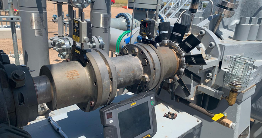
In 2019, JetTech Mechanical LLC was hired to perform maintenance for NGL Pipeline in Colorado. They serviced several SPX Clyde Union Pumps, BB3-D12X12X17W 2 stage 3250 HP, and 3775 RPM, pumping at 7525 US GPM 2000 Ft of Head. Part of the service was to remove and replace the pump’s opposite drive end thrust bearings. The bearings were SKF 7313BECBMs, the installation was back-to-back. To remove the bearings, two jaw pullers were used, and to replace the bearings a SURETHERM 10X induction heater with two temperature probes was used to precisely heat and demagnetize the bearings for installation.
Previously a different portable induction heater had been used, but it took much too long, the heater itself got hot and it only had one temperature probe. The great advantage of the SURETHERM bearing heater is that the twin temperature probes let you precisely monitor the difference between the inner and outer race temperatures and keep that differential to a minimum in order to prevent stressing the bearing.
On the first install, the bearings were heated to 225 degrees Fahrenheit; this took approximately 2 minutes from ambient. The largest possible crossbar that fit the bearing ID was used. One bearing at a time was heated and installed within 6 minutes. No appreciable temperature difference was observed in this case, which gave rise to the greater efficiency experiment we tried next.

The experiment was to see whether on the second installation two bearings could be heated at the same time, placing one bearing around the post and the other on the crossbar, with one probe per bearing. Once again the induction heater worked flawlessly, heating both bearings within 2 ½ minutes and both to the same temperature, 225 degrees Fahrenheit.

This proved to everybody’s satisfaction the full capacity of the SURETHERM induction heater and its efficiency to heat evenly.
The customer’s conclusion was that the SURETHERM is a lot more efficient than any other induction heater they have used in the past. The fact that the Suretherm uses 2 probes, gives them the confidence that the difference in temperature between the OD and ID can easily be monitored making it safe and precise to heat bearings.
They also discovered that they can heat two bearings at the same time, and having the two temperature probe capability allows them to monitor the temperature of both bearings. Even though it is recommended that only one bearing at a time should be heated.
Thank you Brian Franks with JetTech Mechanical LLC for sharing this case study experience with us!
Download our Induction Heating Procedure – Bearing Mounting to learn more about how you can install your bearings properly in a simple and safe way.
by Diana Pereda
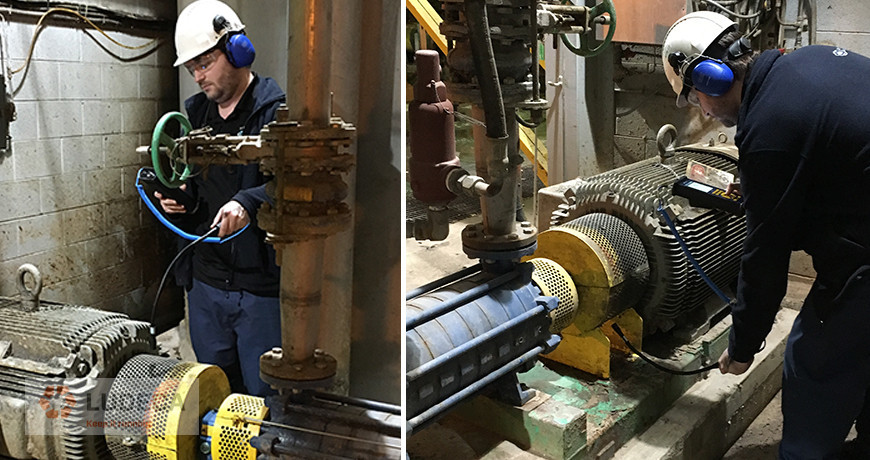

Simon is a condition monitoring specialist from a local oil refinery. He contacted SDT for advice on predicting flexible coupling failures. Currently, they perform condition monitoring on their pumps and motors using vibration analysis. They identified most bearing failures in time but could not detect coupling defects; there was no safe place to mount a contact sensor. Several unexpected failures caused shaft damage and unplanned downtime.
Within the facility they identified 58 pump systems considered “A Critical”, meaning if they go down, the plant goes down. I suggested ultrasound as a fast, safe, and affordable coupling monitoring solution. The model I recommended not only provided Simon with a means to observe couplings, it also measures vibration, eliminating the need to carry two data collectors.
Vibration analysis performs poorly on flexible couplings for two reasons. First, there is no suitable contact point for an accelerometer. Second, the primary defect symptoms of a defective coupling are friction and impacting. These are best detected with ultrasound. An airborne sensor placed near the coupling quickly detects problems. If necessary, Simon can capture a dynamic measurement and trend the defect as it worsens. The SDT270DU gives Simon two choices. He can periodically check for defects (Good) or Simon can integrate all 58 couplings into his established bearing routes (Best).
I explained to Simon how several clients already trend couplings using the Flexible Wand. The SDT270 collects a STATIC ultrasound measurement that gives four indicators of the condition. The first two – Overall RMS and Max RMS – indicate the level of friction produced by the defect. When these indicators rise, maintenance may consider corrective alignment during a planned shutdown. The second two – Peak and Crest Factor – identify the emergence of impacting. Together, all four indicators establish a lifecycle trend for each coupling.
Once impacting appears, the Peak indicator increases in step with Overall RMS. Since Crest Factor (CF) is a ratio between RMS and Peak, a rising CF indicates that the window for simple maintenance has narrowed. At this stage, inspectors collect a DYNAMIC measurement. The DYNAMIC measurement gives a visual representation of friction and impacting severity using the time view. For both STATIC and DYNAMIC measurements, it’s important to define the signal acquisition time.
User-defined signal acquisition time, available exclusively on SDT instruments, is a luxury that lends ultrasound technicians the highest level of precision. Without the ability to set the sample time, inspectors must guess when to pull the measurement trigger, and then question the validity of their data. Simon explained that all 58 pumps turn at speeds above 1800 RPM. Accordingly, he should set his SDT270’s signal acquisition time to between one and three seconds. This guarantees data samples over 30-90 shaft revolutions.
Shaft couplings are guarded for safety and ultrasound inspectors working around rotating equipment must follow company safety policies. SDT designs safety considerations into their solutions. The Flexible Wand’s 10mm diameter sensor allows access to couplings without the need to remove safety guards. The 21” long sensor sports a comfortable, ergonomic grip that keeps the inspector’s hands at a safe distance.
Simon seemed convinced but wanted to #HearMore. Since this solution was already working well at a nearby paper mill, I introduced Simon to the plant manager, Sunil, and invited them both to lunch. Sunil and Simon connected on many common reliability issues that afternoon. He confirmed the affordability of this solution based on coupling failures alone but went on to explain how their mill was rolling out ultrasound for acoustic lubrication, steam trap monitoring, electrical inspection, and air leak management. Simon and Sunil continued their conversation well into the afternoon. They agreed that ultrasound, with its 8 application pillars for reliability, represented a fast, safe, and affordable technology with the potential to revolutionize reliability culture. I sat back, happily watching two passionate specialists strategize about reliability culture. I love my job.
Related Blog: Ultrasound for Coupling Inspection? Yes!
by Diana Pereda
Repost from Benchmark PDM Maad Blog

Let us review this case study on a common issue when working on a pump and motor alignment done by Brian Franks, Owner and Field Service Technician of JetTech Mechanical.
He begins in the normal manner entering the distances of the machine. As you can see this is not a small machine (see Figure 1 below) – there are 57 inches between the motor’s feet and if you add all the measurements together you have 87 inches from the Stationary laser detector unit and the back foot of the movable machine (motor). Notice also that it is a spacer coupling.
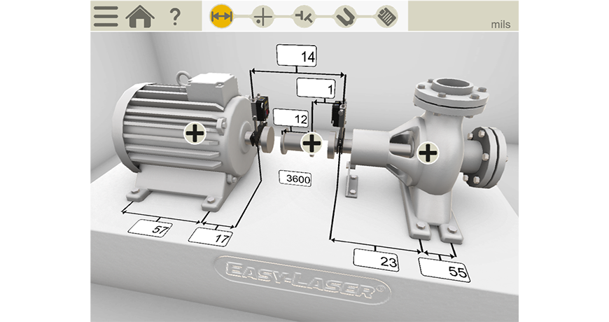

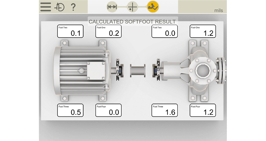
He continues doing the alignment work by taking a soft foot measurement on each of the machines and as you can see, there is very little, so we know it’s a stable base that the machine units are sitting on.

An important note is that they would need the coupling open/loose and the pipe disconnected in order to do this correctly.
The new ANSI standard (ANSI/ASA S2.75-2017/Part 1) allowable soft foot tolerance is two thousandths (0.002 thou or 2.0 mils) of shaft deflection and he is below this, so he is good to go. He documents it for his report.
He now performs the machines’ shaft to shaft alignment.
Notice that he’s removed most of the bolts from the coupling in order to allow the coupling to flex. This is a stiff coupling so you don’t want it locking up during the alignment and you also want to make as few moves as possible. So, this is a good practice. This also tells me they know what they are doing which is good.
The tool they are using is an Easy-Laser XT770 which is a dot laser system that can read in the horizontal and vertical plane.
Click here to read the entire case study “A Case Study on Why Pipe Strain Needs To Be Measured”
by Diana Pereda


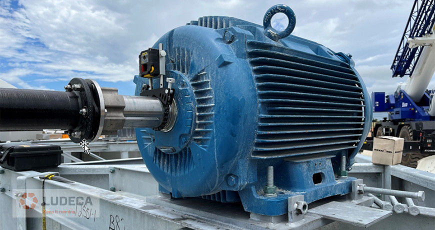
Commenting to Ana Maria Delgado CRL with LUDECA, about the bearings and the lubricants that keep them operating, it occurs to me to write about a point of view that few people observe.
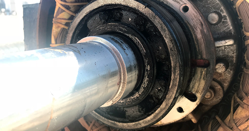
When we talk about lubricants, and regularly when referring to bearings, we talk about grease. Where the grease really performs its work, is at the point of contact of the ball or roller and the inner or outer race. The rest of the grease in the bearing housing does not perform lubricant work. The problems begin when we have to re-grease it, the regreasing of bearings is very particular, the type of grease, the correct amount, at the right time. This is something we hear in lubrication training, particularly on the way to World Class Lubrication. However, when you know the tools of Lean Six Sigma, you are always looking for the True Root Cause.
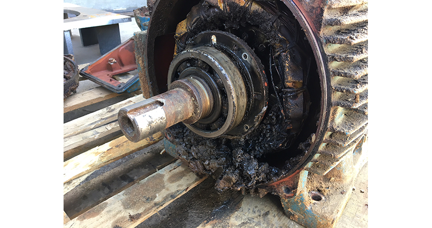

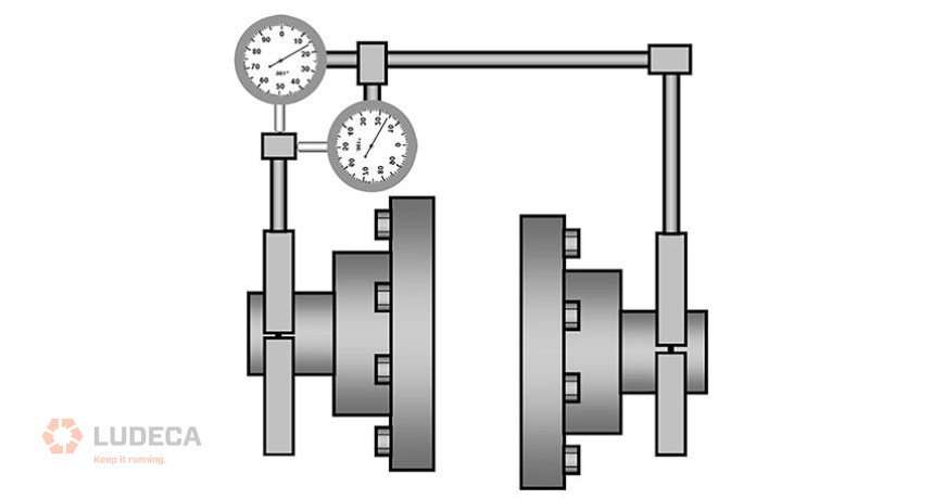
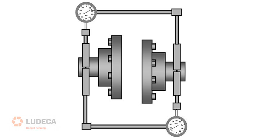
But at some point we have thought about the bearing housing, where the grease enters the housing, what is the route to the bearing, and more importantly where the grease residues damaged by time and temperature leave, not counting current discharges in the case of electric motors. In that passage, it is important that the grease that enters displaces the grease inside the cavity, that the grease that enters pushes the grease that is between the ball and the track, thereby relieving the bearing load. Not being less important that the grease that has finished its useful life goes outside, it does not lead to the winding in the case of electric motors.
If we stop to think about the cavities of the bearings, there are many readings about it, but a writing from Heinz P. Bloch P.E. comes to mind, for a Pump Symposium in 2015, “Lubrication Delivery Advances For Pumps and Motors Drivers”, One of the best writings on the topic of bearing lubrication, thanks to H. P. Bloch, I recommend you read it. This paper puts you to think about the importance of the passage of grease through the bearing and how it has to be allowed to evacuate the grease that has ended its useful life inside the bearing housing.
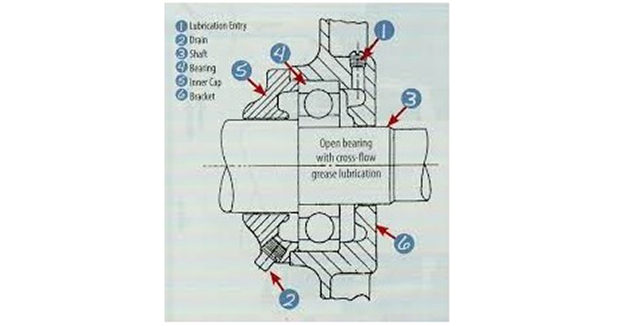

Of all types of bearing housing, only the one that allows cross-flow of grease when lubricating is ideal. When add grease to a bearing the grease under hydraulic pressure of the gun will move through all possible cavities, but if we give a relief on the opposite face of the bearing where the grease entry is, then it will do its job, to remove the spent grease and accommodate the new grease between the ball and the inner and outer race, extending the useful life of the bearing, avoiding maintenance interventions, improving productivity.
Reading the letter of Mr. Heinz P. Bloch, reminds of an old friend his beginnings in the industry, when he just graduated from college, he was in probation and have to go through the different facets of Manufacturing, and then Maintenance, he had to work directly with an industrial mechanic, who did not like to teach, therefore he had to learn by looking, without asking questions, he forced it, “which he thank him ”, to look at all the details in the mechanical assets, how many threads the screws have, the size of the pipe, if the bearings were balls or rollers, where the grease enters the bearings in the electrical motors, the right tool for the job, etc.
He forced him to speak the language of the bearings, to touch them carefully and capture the operating temperature, to make contact with the nail and appreciate the vibration, to listen and smell the condition of a rotating asset, it is interesting.
The grease has to come into contact with the ball and the track, if the Bearing Housing does not allow the new grease to displace the old grease and come into contact with the ball and the track, the bearing will fail, it will be long term but the fatality will occur, or you will have unwanted mechanical interventions of rotating assets. The training of technicians who perform the lubrication task is very important, for them to understand this.
by Diana Pereda

Our colleges at Benchmark PDM recently had a request from a customer to do some pump alignment. When we normally think about pump alignment, we usually think of shaft to shaft alignment. In this case, they wanted bore alignment. They were installing a brand-new pump and when they rotated the shaft, they could hear grinding.

After further inspection one of the techs could see that the bearing housing had been moved – either during shipment or when it was stored. They could see that the dowel pin had been damaged.
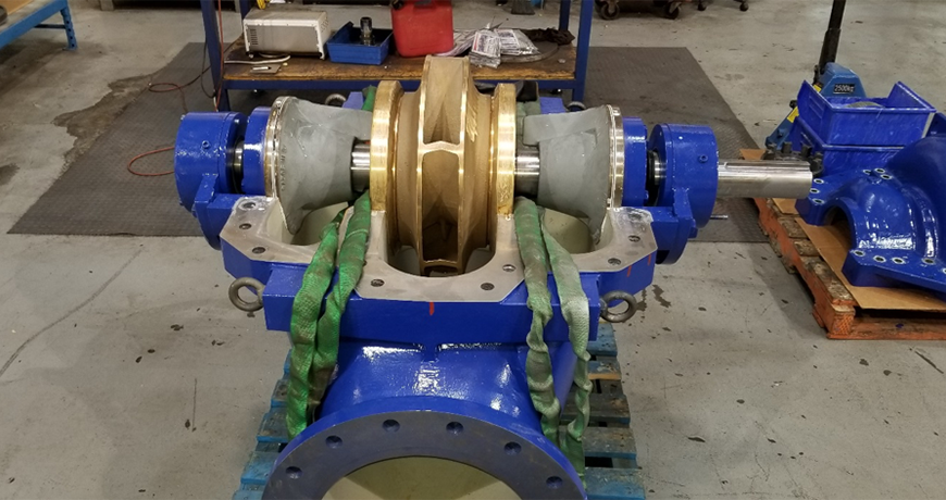

Figure 1
If you pop the lid off this style of pump (See Figure 1 – photo courtesy of KSB Pumps Canada), we see the shaft and the center mounted impeller. On each side of the impeller we have the wear rings, which sit in the bores. Outside of that we have two stuffing boxes or seal bores and outside of these we have the bearing Journals which are also bores. All of these bore centers need to be colinear, meaning in a straight line.
The old traditional methods for doing this type of work was done using piano wire or a mandrel. They would use the stuffing box or the wearing bores as reference points then measure to see if the bearing bores where in alignment. This method was “hit and miss” because its so difficult to set up and measure in this way. It also took a very long time.
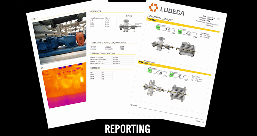
Using a laser-based measurement system has significantly reduced the time taken to do bore alignment. More importantly, it has improved the accuracy significantly. There are now automatic reports that go with the final bore alignment that has been completed – a documented history of the work is very important.
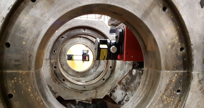

Figure 2
There are many different applications where bore alignment is done using lasers. For example, extruder barrels that need to be aligned to a gearbox in the plastic industry, crankshaft bearing journal bores in diesel/natural gas engines or compressors in the oil & gas and energy industries and stern tube alignment in the shipping industry. These are just three examples that show how varied the type of alignment work is.
Click here to read the entire case study “Bore Alignment on a Split-Casing Pump”
by Diana Pereda
I’m sure you have heard how important precision maintenance is to the health of your equipment, but have you ever seen the real impact it has? Recently, to show this point within my company, we did some training to demonstrate how restoring a machine into a precision state can make a real difference.
We divided a training class into five groups. Each group focused on bearing installation, alignment, fastener torquing, balancing, belt alignment, and other precision maintenance practices on machinery. The chart shows the impact of precision maintenance and why it is so important. Notice how the vibration, temperature, and amperage was reduced as each machine was brought into a precision operating state.
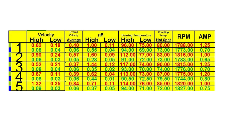

Red values are the as-found measurements for each machine/group and green is the as-left condition after the precision maintenance activities were completed. These were not large machines, but this clearly shows how taking a little extra time and care with equipment will reduce the operational stresses, reduce wear and failure conditions, save energy and improve reliability.
Often we focus much of our time on defect identification, planning, scheduling and elimination (repair) of equipment defects. These practices must be executed properly. However, we tend to overlook the importance of restoring and keeping our equipment in a precision operating state so defects are not created in the first place.
Visit our Knowledge Center for resources and tools to help you succeed when implementing and using our maintenance technologies! Watch our video tutorials, download infographics, plus explore other helpful information to reduce equipment failures and downtime.
Related Blog: What is your company’s definition of “Maintenance”?
by Diana Pereda
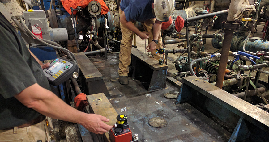

When you are installing a new machinery in a facility of the organization, there are certain issues. These issues are listed from top to the bottom categorized on the basis of seriousness. The top of the list is shaft alignment. It is the most common issue while installing the machinery. It occurs due to lack of training or of precision instruments, as well as measurement misconceptions. Most organizations think they have achieved alignment just because an instrument showed so. They don’t take the stress and heating mechanisms into account which causes misalignment between the colinear wings of the shaft.
The second issue is the measurement in the base. The machinery installation should start with the removal of stress. The best place to start doing this is by making sure the base is level and flat. You can’t just use any off the shelf leveling tool for that. You need to stick to the height and level measurements from the surface. The third issue is soft-foot. It occurs when one foot of the machine is not in level with the other one. It can cause distortion in the machine casing. It also affects alignment measurements when you are checking for correctness. Download our Soft Foot: Causes, Characteristics and Solutions for the in depth causes and characteristics of soft foot conditions and how to diagnose and solve them
Then comes the pipe strain that causes shaft deflection and case distortion that leads to pump failure. So, you need to avoid putting stress on the pipe. The next one on the list is offline to running. It occurs because of thermal growth in the machine. You can change operating temperature for reducing the initial start-up tork. But there will still be some amount of tork that can lead to this issue. The sixth issue is coupling run-out and machine looseness. It causes vibration in the machine just like misalignment. You can find it out using a dial indicator. You should look for the run-out in coupling and also check the bearings. Watch our Shaft Alignment Know-How video to learn about the effects of running equipment with pipe stress
The number seven is moving the machine. You need to have control when you are moving a machine to avoid sliding. You can use jacking-bolts for that but you need to check the integrity of the bolts as well. You can use the laser to fix this issue or by using graph paper to show how to optimize the machine movement. The next issue is hardware because it makes a lot of difference. Use of poor hardware like nuts, bolts, and key chains can cause machinery issues too. You also need to use proper tools while tightening the bolts and make sure they are calibrated right for the job.
All of this depends on the training because they need to be able to use all the necessary tools. They need to have the proper training. They should be able to do more than just pushing the right buttons. They need to be guided about the proper machinery installation. They should be trained at a standard level for this. The last but not the least thing is to have proper documentation of the quality measures that are taken because it helps you understand the operational phase of the machine.
Thank you James Kovacevic with Eruditio LLC for sharing this [podcast] with us and John Lambert with BENCHMARK PDM for his excellent knowledge on machinery installation!
by Diana Pereda


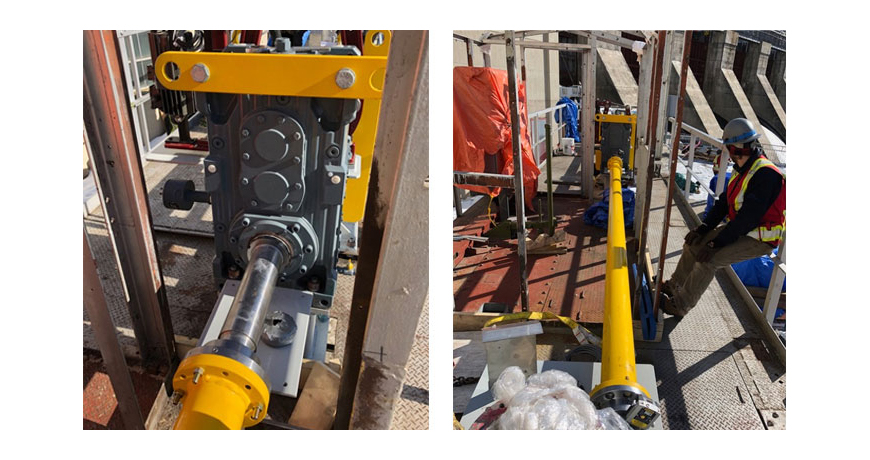
When you are working with nature, you treat it with respect. And that’s what this dam facility on the Kootenay River in British Columbia does (image, above left). When you harness the power of a river you need your control systems to work. The spillway gates control the level of the dam and in this example, it is lifted and lowered by two Worm Drives that are approximately 33 feet apart, so it’s a large gate. Pictured (above right) is one of the worm drives.
The drive motor and gearbox are mounted in the middle and the complete system is being replaced. As with any machinery installation work there will be a lot of alignment work required, including the two drive shafts which are 176 inches in length.
Chad Hansen of CH Mechanical was asked to do the shaft alignment work on the complete drive. Chad owns an EASY LASER XT660 shaft alignment tool which can cover a measurement distance of over 66 feet. He is confident he can do this work however, as the largest span from worm drive to worm drive is 33 feet. But the work doesn’t start on site, it starts back in the shop.
This is the drive assembly (image below) for the two jackshafts that drive the worm drives, which opens/closes the gate. A new base had been fabricated, which in its self is a nice piece of work! Notice that it has four different levels with machine components attached. That’s 8 mounting foot pads, one for each mounting bolt. Each of these mounting surfaces should be flat. Each set of mounting pads should also be coplanar; for example, the four foot pads for the motor should be flat. I could go on about the importance of base flatness but i’ll leave that for another post!)
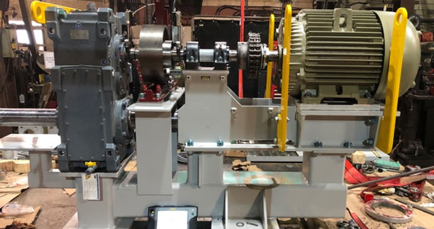

Now let’s look at the machine’s components. A good-sized motor with standard mounting feet has a shaft coupled with a chain coupling. This connects to the short spacer shaft supported by two pillow block bearings. This is coupled with a flange-mounted rigid coupling which then connects to a drum brake that is mounted on the gearbox input shaft. Now for the gearbox. The one output shaft is obvious, coming out of the front side of the gearbox (left side of image) with the shaft parallel to the motor shaft. The other shaft is harder to see, on the opposite side, under the drum brake pedestal running underneath the motor. The motor and pillow block base will be removed during the installation but this pre-assemble is to make sure it all fits without being bolt-bound or base-bound.
The most important aspect of this machine’s installation is mounting the gearbox and setting the brake, and that where Chad starts. The gearbox input shaft must be parallel with the mounting surface of the brake. This can be achieved by shimming the gearbox and/or the brake. It’s usually a combination of both to get the optimum move but its time well spent. The end goal is that there is no gearbox shaft deflection when the brake is applied. This means no angle or offset. Next, the spacer shaft is aligned to the gearbox shaft. This is a rigid coupling, so it is best to do this with the coupling open (separated). This is done by using the two built-in electronic inclinometers in the measuring units and either the 9-12-3 measurement method or EasyTurn measurement method. Either way you get a high accuracy, repeatable alignment.
After this you can align the motor to the spacer shaft. With the Easy-Laser XT660 Shaft Alignment tool Chad has different measurement method options because this alignment work is important. Here, he can use the multipoint measurement method and take a series of measurements. He can align the motor to the spacer shaft then go over the top to align the motor to the gearbox shaft, his choice. He can use the new ANSI standard tolerances which is in the display and will be shown in the report.
The whole gearbox and drive assembly are installed on site. However, the bearing pedestal, motor, and motor base has been removed for easy access (image, below left).
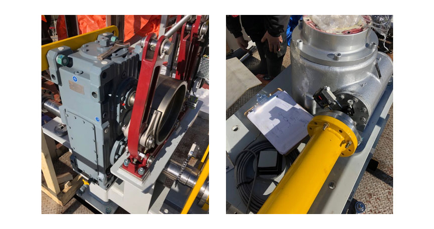
 The right-side jackshaft is installed first, that’s the one closest to the dam. You can see the moveable laser/detector unit mounted on the output shaft just below the drum brake. The worm drive (image, above right) will be the stationary machine with the other laser/detector mounted. The laser alignment data is collected using EASY-LASER’s EasyTurn measurement method with the results showing the amount of misalignment and in which direction they need to move the machine.

The alignment work is completed. There is a little wiggle room at the worm drives however, most of the corrections are made by moving the drive assembly. CH Mechanical uses the new ANSI alignment tolerance for spacer/jackshafts. They are well within spec so it’s a job well done. The actual numbers remain the property of the Dam, so we won’t publish them. However, there is a lot of margin on a 176-inch shaft length. That’s not to say that it’s a quick job, its not. Its actually a very complex job made easy by Chad Hansen and his EASY-LASER XT660 shaft alignment tool.
Thank you John Lambert with Benchmark PDM for sharing this successful story with us!
by Diana Pereda
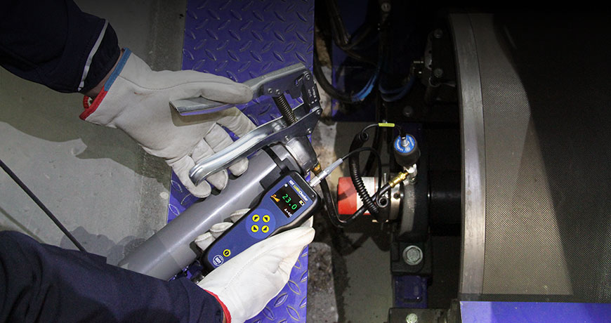

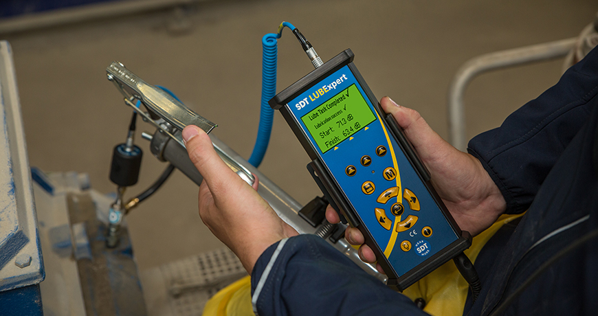
Ultrasound is a guide to precision grease replenishment in motor bearings. It is also known for its versatility for leak detection, valve assessment and electrical fault detection.
Acoustic lubrication is an integral component of ultrasound programs. Fewer than 95 percent of all roller bearings reach their full engineered life span, and lubrication is the culprit in most cases. In fact, poor lubrication practices account for as much as 40 percent of all premature bearing failures. Yet, when ultrasound is used to assess lubrication needs and schedule grease replenishment intervals, that number drops below 10 percent. What would 30 percent fewer bearing related failures mean for an organization? Download our 5-STEP Acoustic Lubrication Procedure – An effective lubrication procedure to grease bearings right
To understand the role precision lubrication plays in bearing life extension, it helps to understand basics of bearings, their lubrication mechanism and how ultrasound helps.
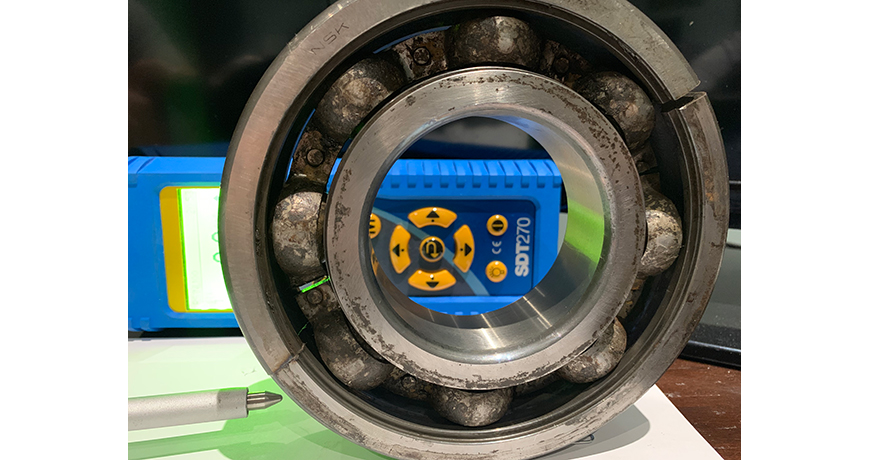
The insides of a bearing consist of four components. The inner and outer raceways form a path for the rolling elements to glide on a thin film of lubricant. A metal cage separates the rolling elements, keeping them evenly spaced to distribute the load and stop them from crashing into one another. These components move in concert producing frictional forces from rotational inertia, surface load, misalignment, imbalance and defects. Zero friction is impossible, but optimal levels of friction are achievable with correct installation techniques and proper amounts of lubricant. Download our Induction Heating Procedure – Bearing Mounting – A simple and safe procedure for proper bearing installation
Ultrasound works on the FIT principle—it responds well to defects that produce friction, impacting and turbulence (FIT). For motor bearings, two of these phenomena apply: friction and impacting. Ultrasound detects high-frequency signals produced when two surfaces slide together or come in contact with any force. Stage 1 bearing failures happen at the micro level. Because ultrasound ignores low-frequency audible signals, it forms the perfect companion for measuring, trending and analyzing defects despite high levels of noisy interference encountered on the factory floor.
Ultrasound detectors detect friction and impacting as acoustic energy from rolling friction and defect impulses. When lubricant levels are optimum, the energy created is at its lowest. As frictional forces increase, so does the acoustic energy. Ultrasound instruments measure friction and impacting as energy using the scaled value dBµV (decibels/microvolt). The results are presented as condition indicators, and there are four of them:
Condition indicators are most responsible for transforming ultrasound technology from a simplistic, “point the gun and pull the trigger” gadget, to being recognized as analysis and trending technology. Condition indicators add validity to trending by going beyond the single decibel. If a user currently uses an ultrasonic gun that does not have condition indicators, they should question the data. Click here to read the entire article “Use Ultrasound to Optimize Grease Replenishment”
by Diana Pereda
Understanding the Key Components of an Effective Lubrication Program
Lubrication is often overlooked in organizations. Why it is overlooked, I am unsure. Maybe it is because it is considered to be a basic job, given to the apprentice, or it is just too simple not to do it correctly.
However, with a focus on lubrication, many failure mechanisms can be reduced and the equipment life prolonged. But implementing an effective and world-class lubrication program is not simple. It requires a dedicated focus to implement and sustain. Below is my list of what I look for when evaluating a lubrication program.

Effective lubrication takes many of the practices mentioned above and provides a governance framework to support and ensure it is executed as designed. With an effective lubrication program, the organization should see an increase in uptime, a reduction in lubrication consumption, and a reduction in the number of lubricants on site. These changes enable the organization to operate more efficiently.
Next Steps
To begin the journey to improve your lubrication program, you do not need a full assessment and massive project. Take one of the items above, learn more about it and start a pilot. Make sure to build a business case with your pilot to capture the benefits and use that as a basis to build the business case for the larger project.
Thank you James Kovacevic with Eruditio LLC for sharing this informative article with us!
by Diana Pereda
We used to assume that once equipment is installed and aligned, it will remain in the same position forever. But this is not always the case.
The alignment should be checked periodically. This valuable information will help you to find problems like pipe stress, unstable foundations, weak frames and loose bolts, among other problems. All the efforts to align your equipment and keep it within tolerance will be worthless if your machinery can’t keep its position. Therefore, the repeatability of the alignment check is your best ally to see how the equipment behaves.


How often should you check?
There are guidelines for how often the alignment should be checked. According to John Piotrowski in his Shaft Alignment Handbook, for newly installed machinery the alignment should be checked after 500 to 2000 hours of intermittent operation, or 1–3 months of continuous operation. If there was no apparent shift in the alignment, then next check should be made at between 4500 and 9000 hours of intermittent operation or 6 months to 1 year of continuous operation. If no apparent shift occurred at any time, then checks should be made every 2–3 years. This interval can of course be influenced by factors such as equipment criticality etc.
If a moderate shift in alignment occurred at any time, then the equipment should be realigned to within acceptable tolerances. If a radical shift occurred, then additional investigation should begin to determine what is causing the shift – a root cause analysis. For example, any indication of excessive wear and tear will also be an indicator of a “non-healthy” machinery installation.
The importance of documentation.
To have properly documented alignment checks is essential to avoid repeating the same installation errors, or to discover and follow up on recurring problems. Of course, there is no exact answer to the headline question. But the documentation will give you a very good understanding of what happens along the way, and help you keep your machinery aligned as long as possible.

Thank you Roman Megela with Easy-Laser for sharing this informative article with us!
by Diana Pereda
We’ve all read about it: leak detection should be a top priority since leaks can account for up to 30 to 40% of consumed volume… So, why is this issue still on the table? Why is it difficult to change things in the field?
In industry, one of the most common applications for ultrasonic detectors is to search for leaks to achieve greater energy savings. For both service providers and maintenance engineers, the hardest task is not so much to localize the leaks, which is child’s play if you have the appropriate tool, but to generate a report of the problems found, organize the required repairs and communicate the resulting savings to management and others within the company. A company-wide cost reduction program will be efficient only if all stakeholders are involved. When the implementation of an efficient program aiming at minimizing the energy costs related to compressed air fails, it is not due to technology, which almost never fails, but to human factors. All surveyed companies that had initiated a leak detection program that did not last over the long term had something in common: a lack of communication.
The successful implementation of an energy-saving strategy relies on good communication between all stakeholders, directly or indirectly. What you need to do is involve five different persons or groups, each having a very specific role to play in this campaign. The first person is the Ultrasound Inspector: he/she knows the network and where to find the losses. The second person is the Purchasing Officer: he/she buys the equipment required to manage the program and possibly negotiates power supplies. The third person is the Maintenance Planner: he/she will schedule the repairs to be done after inspection of the network. The fourth group is the Maintenance Supervisor and Technician(s) who will repair the defects that have been localized. The fifth person involved is the most important one: he/she is the Executive Sponsor whose role is to motivate and drive the project and communicate the savings achieved to all concerned. By highlighting these savings within the company, he/she will make the project come alive with visible and measurable results.
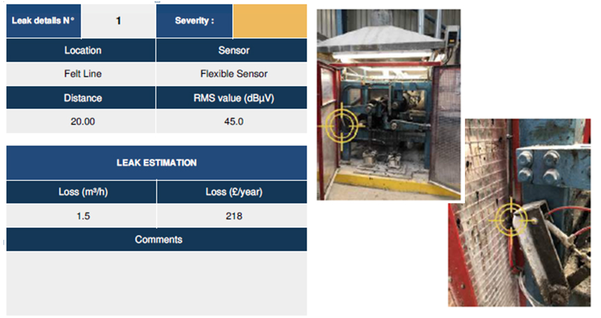
It’s easy to say, but in reality takes a lot of time and organization. However, since the advent of smartphones, tablets and other connected devices in the maintenance world, you can now use free assistance tools available as iOS/Android applications to measure leak-induced costs and document them with pictures. These applications can also be used to assist the various stakeholders and monitor the different steps to complete the implemented program (e.g., LEAKReporter, LeakSurvey). These tools are now able to automatically assess the costs of the defects detected over an entire year. Communication between all departments affected, directly or indirectly, by the program is now simple and natural.
In 2018, we worked with a company located in the North of Manchester, England, which, for many years, has used measuring instruments to detect leaks. However, no energy savings have been observed nor measured. As a result, the team was experiencing a loss of motivation and had given up on its cost reduction strategy. Thus, our customer’s request was simple: give a new life to their projects. The first steps consisted in clearly redefining everyone’s role. The second step was to train the team in the use of newly available tools: leak detector and mobile applications. The third step was to set up a “think tank” inviting all stakeholders to reflect on the best approach to adopt to manage and organize a leak detection campaign before, during and after our intervention (see diagram below). Finally, the fourth step was to celebrate our results with all the persons involved in the project. After two days on site, everyone precisely knew what was expected of him/her. 17 leaks were localized, representing potential yearly savings of 3,934 GBP (4,481 EUR or $5,111 US) and, after the quick repair of 7 leaks; actual savings of 1,648 GBP (1,877 EUR or $2,142 US) were quantified. As a result, the inspector has a better control of his/her network and of compressed air losses and actual needs; the purchasing officer can calculate the return on investment; the technician feels valued by the savings generated from his/her work; and finally, everyone is thankful to the sponsor for (re)establishing communication between the different departments.
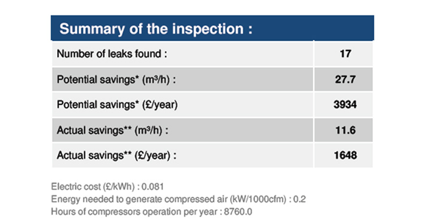

Automatic savings sheet and automatic work order were generated by the SDT LEAKREPORTER mobile application.

Loss (£/year) = $249 US
We also share with you our LEAK MANAGEMENT: FIND-AND-FIX LEAKS PROCEDURE: An effective way to survey your systems and detect leaks.
Thank you Benoît Degraeve with SDT Ultrasound Solutions for sharing this case study with us!
by Diana Pereda
It is important to ensure that the top cover mounting surface, machine sole plates and rails, and main bearing “landings” of a compressor frame are installed as flat as possible. This ensures that the main bearing bores and internal components remain undistorted and aligned as per their factory specifications.
Ariel Compressors have a strict tolerance for the top rail alignment, and their ER-82 document discusses this in detail. Essentially, if the top rails are flat, the main bores will be as well, and provide a proper run condition for the crankshaft and bearings. There are many ways to perform a flatness check so long as the equipment used meets the Ariel guideline for accuracy. Some people have chosen an inclinometer-based system but systems like the Easy-Laser XT770G add a new dynamic in versatility. When checking a large frame like an Ariel KBB the XT770G gives the user consistent, reproducible measurements they can trust to make critical adjustments. By looking at the elevation of individual points, instead of the rise-over-run between them, the actual repair is made much easier.

The initial setup of the XT770G for a top rail measurement is simple. Because the Laser Transmitter is on a magnetic tilt table, the system can be put anywhere within line-of-sight for the rails to be measured— even on the rails themselves. Either a plate or a tripod may be used to position the laser. Before placing the sensor on the rail via magnet, you want to make sure the rails are clean and free of debris or excess oil. Once the rails have been cleaned the XT770G is bucked-in, to establish a plane that is reasonably parallel to the surface of the compressor. The system is now ready to take measurements for the required points. The number of points is determined by Ariel, based on the frame model.
Once set up, measurements with the XT770G take less than 5 minutes on a KBB frame or other large scale compressors, due to the freedom of a powerful Bluetooth connection. With the measurement data recorded, adjustments can be made by viewing the information in the rugged XT11 computer or the free iOS and Android applications. Several options are available for referencing the data, such as an All Points Negative, All Points Positive, Best Fit Around Zero, or even Custom Reference Points. These numbers can be plugged into the ER-82 spreadsheet. Reporting may also be done in the field through the USB option, or sent directly to an email address using the Wi-Fi embedded in the XT11 computer. The PDF report is ready to be imported into any work flow management software, keeping all measurements easily documented and ready to archive.


The Easy-Laser XT770G is a true commissioning focused alignment system that is capable of shaft alignment, ER-82 flatness, base twist, belt alignment and simple vibration.


by Diana Pereda
The SDT270 system was used to collect ultrasound data at a methane plant for start-up and commissioning of newly installed equipment to get a baseline condition on the motor’s and gear reducer’s bearings and gears. We were immediately able to pinpoint a defect in the drive end motor bearing using the SDT270 as well as collect and record a sound file (play below) and present it to the customer.
After removal and inspection of the motor bearing it was found that the motor had been stored in a basement and got water into it through the electrical conduit during a monsoon storm that flooded the facility in late summer, causing the bearings to rust and corrode. It was also found that the electrical disconnect box for the motor had water in it as well.

Pump: Progressive Cavity Seepex Pump
Motor: WEG 75HP 1775 RPM
Not only were we able to identify a bearing fault but also the “smoking gun” root cause, thereby thwarting further damage in the electrical system.
After troubleshooting the entire facility we were able to save several other motors stored in the basement that had also had water exposure through the electrical conduits.

Thank you Brian Franks with JetTech Mechanical LLC for sharing this success story with us!
by Ana Maria Delgado, CRL
Thank you Juan R Márquez with Eli Lilly and Company for sharing this informative article on bearing lubrication with us!
Download our Oil & Grease Storage Best Practices which includes helpful tips to outline the best practices for proper lubrication storage.
Related Blog: How to Grease Your Bearings Using Ultrasound?